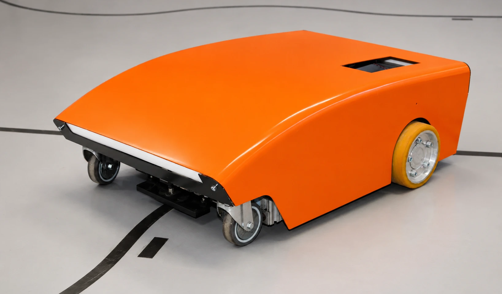
This application note describes the design and implementation of a minimal but full-featured magnetic-guided automated guided vehicle based on the Naviq MTS160 magnetic sensor and the EQSP32 IoT controller. The objective is to achieve reliable guidance and motion control suitable for industrial environments while minimizing system cost, hardware complexity, and integration effort. Magnetic navigation is particularly well suited and cost-advantageous for installations with stable, fixed paths.
Guidance principle
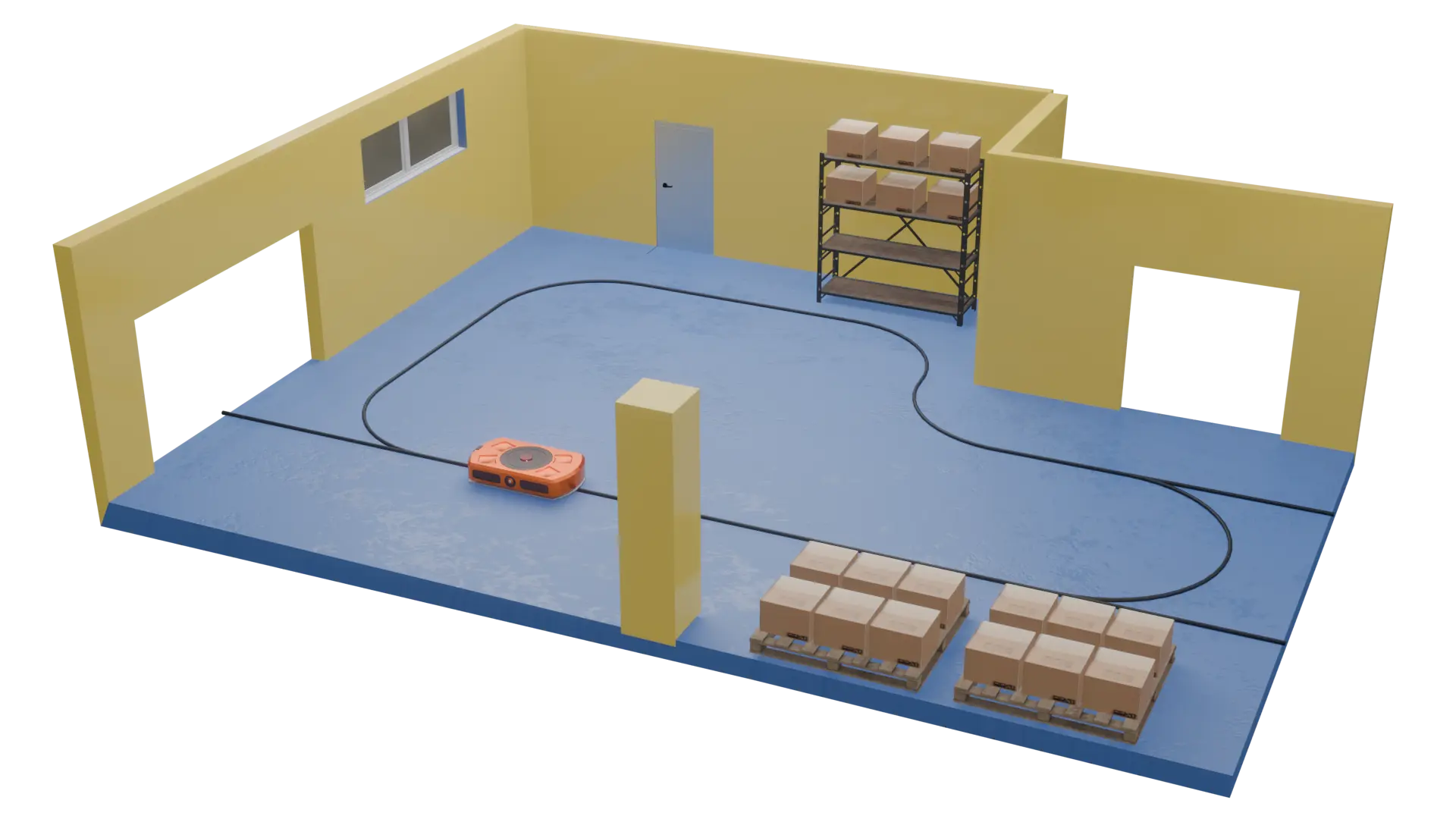
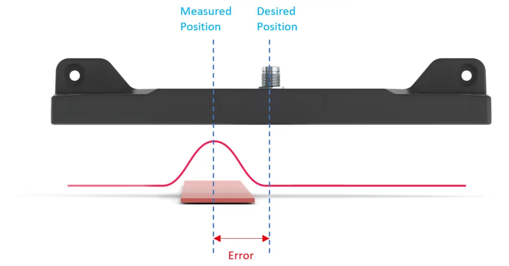
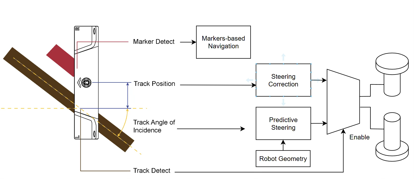
Vehicle guidance is based on a magnetic tape installed on the floor. A single MTS160 magnetic sensor is mounted 20-30mm from the ground and continuously checks the presence of a track, measures its lateral position relative to the vehicle, the angular misalignment between the vehicle and the tape, and occasional presence of location markers.
Sensor to Motors Guidance Principles
The angle measurement is combined with the known robot geometry, including wheel diameter, wheel spacing, and the placement of the sensor, to estimate the curvature of the track ahead. This information is used in a predictive steering block to compute the steering component required to follow the tape smoothly through curves.
In parallel, the track position measurement represents the lateral offset of the vehicle relative to the tape. This value is processed by a proportional control loop that generates a corrective steering term to keep the vehicle centered on the track.
The outputs of the predictive steering and the position-based steering correction are combined and applied to the differential drive mixer, which converts the steering demand into individual left and right motor commands. The track-detect signal acts as an enable condition for the motor output. If the tape is not detected, motor commands are inhibited, ensuring that the vehicle safely stops when going off track.
Marker-Based Navigation
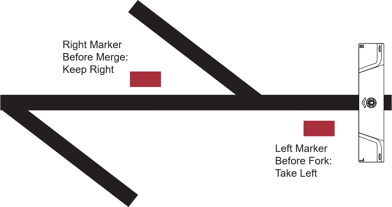
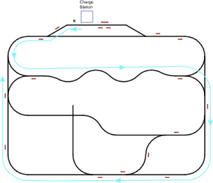
The navigation strategy used in this application relies exclusively on magnetic tape and discrete magnetic markers. Markers are pieces of magnetic track of inverted polarity.
No map, localization, or external coordination is required. All routing decisions are encoded directly onto the floor.
Routing employs a simple, field-reconfigurable marker system:
- Routing Markers: Placed before forks, these indicate left or right path selection. Before merge, they instruct the robot to follow the current path and ignore the merging track.
- Navicode: These are marker patterns that can encode a number up to 16-bit long, using a sequence of left and right markers. The navicode of value 1 is placed before the docking segment to prompt speed reduction and arms point-marker detection.
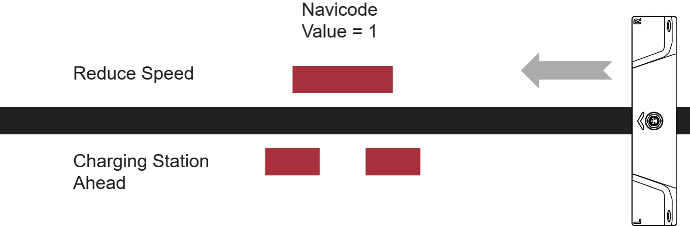
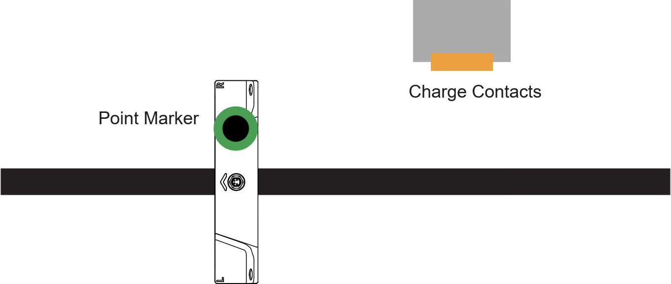
- Point Marker: These are magnetic disks markers that provide millimeter-level longitudinal positioning for precise stopping at the charger.
This very simple combination of track and markers can produce elaborate trajectories and robot behavior.

Track layout with fork selection and location markers
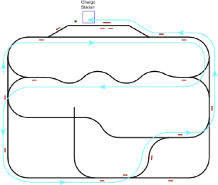
Complete AGV Trajectory
AGV System architecture
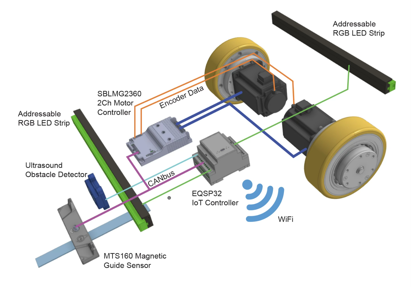
Main system components of AGV
The AGV architecture is built around a 500 kbit/s CAN bus backbone that tightly couples the magnetic guide sensor, an EQSP32 IoT controller, and a dual-channel motor controller. The MTS160 continuously transmits track position, track angle, and marker information. This data is consumed by the EQSP32, which acts as the central control unit, executing the guidance algorithm, state machine, and safety logic in hard real time. It computes left and right wheel speed commands and sends them over the CAN bus to the dual-channel motor controller. The motor controller closes the inner speed loops using encoder feedback and returns odometry information to the EQSP32 over the same bus.
The EQSP32 connects to the facility’s WiFi network for supervisory functions. The controller accepts high-level commands and publishes telemetry data using the MQTT protocol. Loss of Wi-Fi does not affect the real-time guidance or motion control.
The EQSP32 provides low-level access to hardware peripherals, enabling direct generation of high-speed signaling for addressable RGB LED strips used for visual status indication, as well as native processing of an ultrasound obstacle sensor with microsecond-level timing. These auxiliary functions run concurrently with the navigation loop without degrading the deterministic behavior of the guidance and motor control.
Power and wiring
The system is powered by a 48 V lithium and a 24V down-converter, which serves as the main energy source for traction and control. The 48 V battery is connected directly to the motor controller. The 24 V rail powers the EQSP32 controller and the magnetic guide sensors.
The EQSP32 connects to the motor controller and magnetic sensors via a CAN bus, which carries all real-time data, including guidance information, motor commands, and feedback. A second magnetic sensor can be connected on the same CAN bus for rear or reverse guidance if required.
A Run/Stop pushbutton is wired to a digital input of the EQSP32 to enable or inhibit motion independently of wireless commands. Battery voltage is monitored using a resistor divider connected to an analog input.
The ultrasound obstacle sensor’s trigger line is driven by a digital output, and the echo pulse is returned to a digital input, allowing precise time-of-flight measurement for obstacle detection.
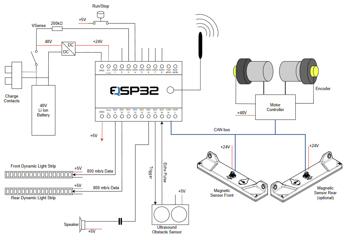
AGV Wiring diagram
Two addressable RGB LED strips, receive a dedicated high-speed data signal (800 kbit/s) directly from the EQSP32, enabling dynamic visual indication of vehicle state, direction, and faults. A small speaker is driven by the EQSP32 for audible feedback.
Wireless communication is provided through the EQSP32’s Wi-Fi interface, connected to an external antenna wich can be mounted on outside the robot’s body for best WiFi range.
Firmware execution model
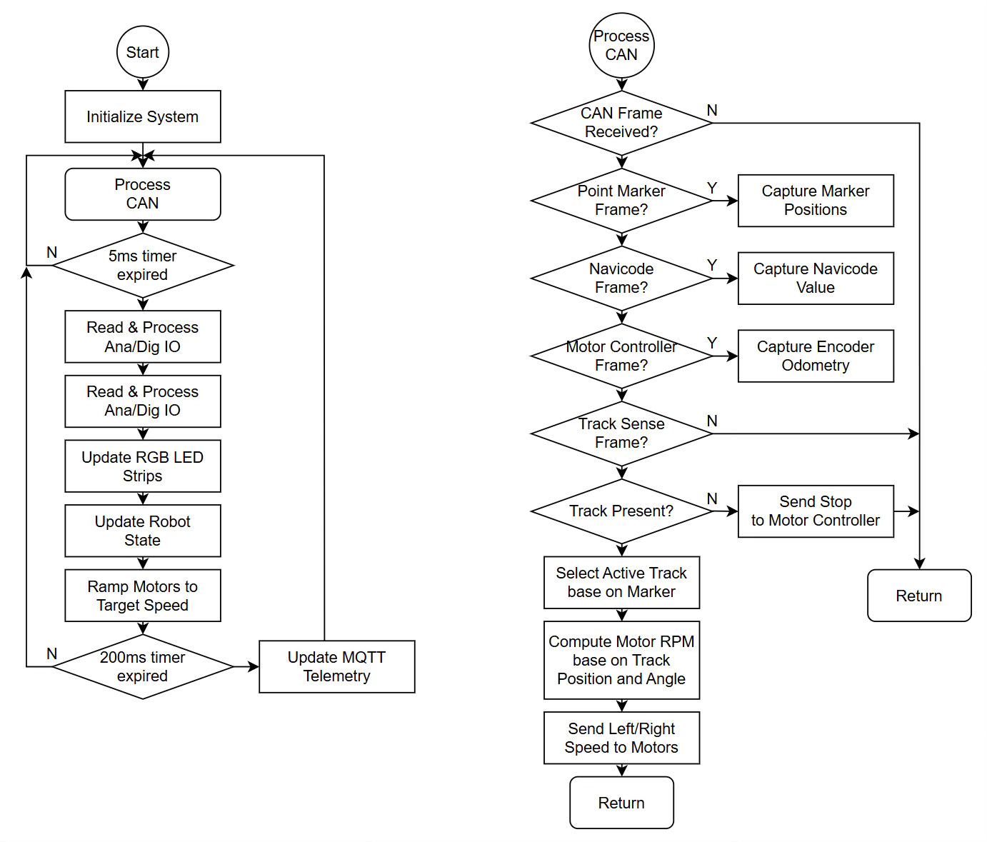
Firmware execution flow chart
The firmware is organized around a fixed-period main loop running every 5 milliseconds, complemented by asynchronous CAN message processing. The periodic loop handles input acquisition, state machine execution, speed ramping, and peripheral updates. CAN frames are processed as they arrive, and guidance computations are updated immediately when new sensor data is received.
Telemetry publication and command reception via MQTT occur at a slower, fixed interval and do not interfere with the real-time control loop. This execution model provides deterministic behavior while maintaining simplicity.
Open-Source code for this AGV is available from Naviq.
State machine and navigation behavior
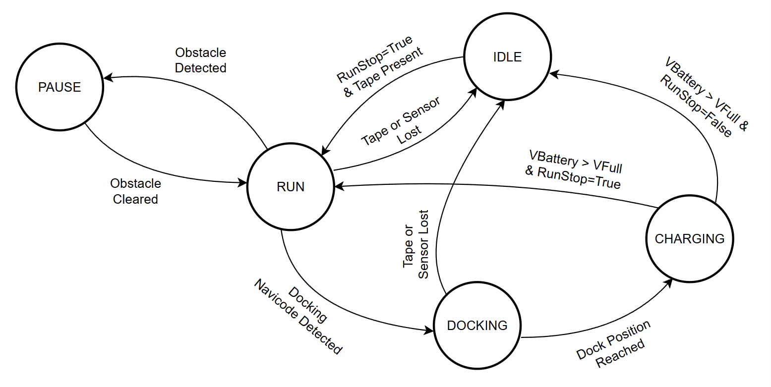
AGV State diagram
Vehicle behavior is governed by a finite state machine. Transitions between states are triggered by operator commands, sensor conditions, or marker detection.
Telemetry and Supervisory Software Description
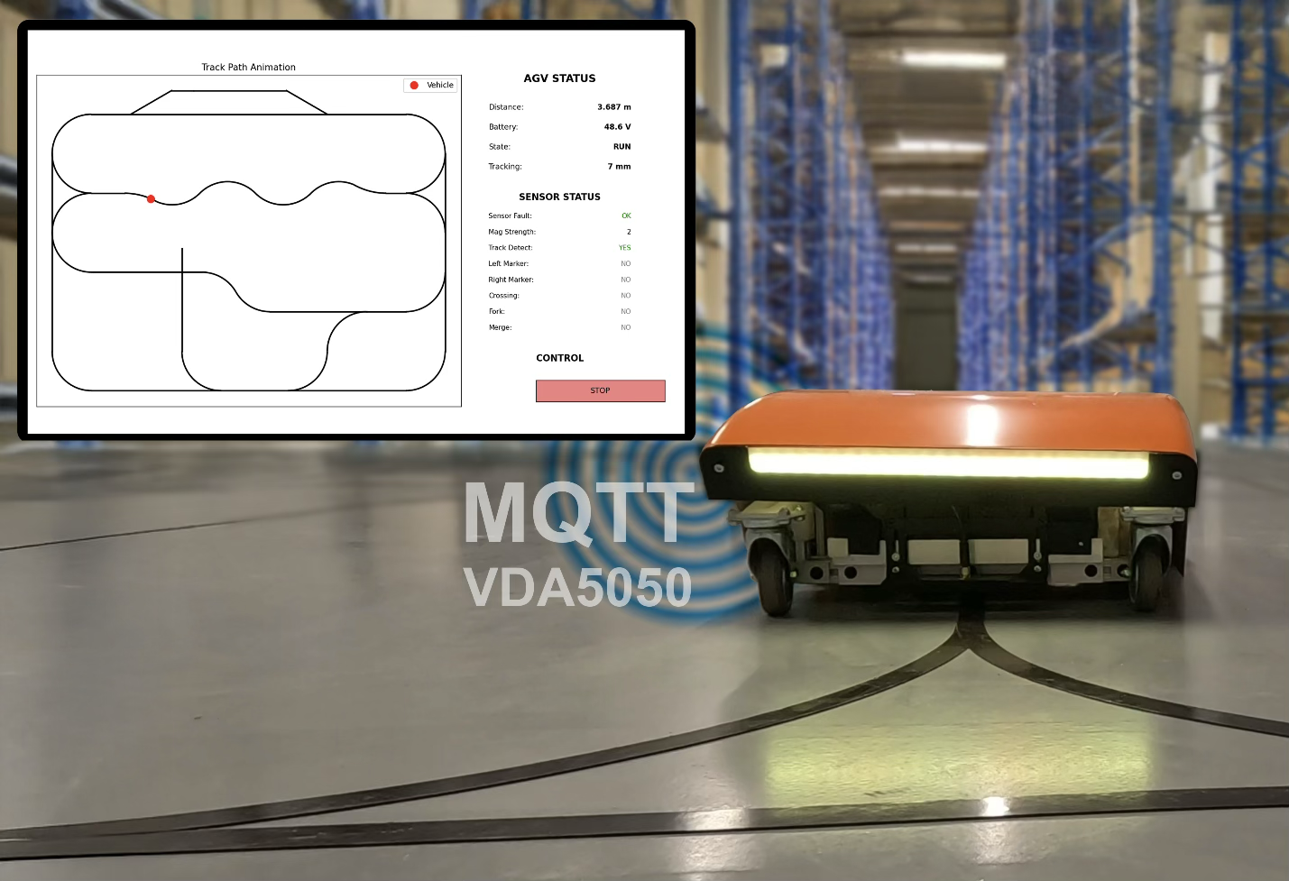
The EQSP32 publishes operational data over MQTT, including vehicle state, tape offset, traveled distance, battery voltage, obstacle distance, and diagnostic information. Remote commands such as run/stop, speed setpoint, and selected control parameters can be received and applied during operation.
While the telemetry implementation in this example uses custom MQTT entity names for simplicity sake, support for VDA5050-style standardized telemetry is fully within the capabilities of the EQSP32 platform. The internal MQTT handler and JSON entity manager can accommodate the VDA5050 mission and state structure with appropriate topic mapping. A future revision of this application note will expand on this with a VDA5050-compliant interface example, including mission state, order updates, and AGV status synchronization with orchestration software.
The supervisory software is a PC-based application written in Python. Its purpose is to provide a real-time visual representation of the estimated AGV position along a predefined track, display vehicle and sensor status, and allow basic supervisory control. The software is not part of the real-time control loop and does not influence guidance or motion stability.
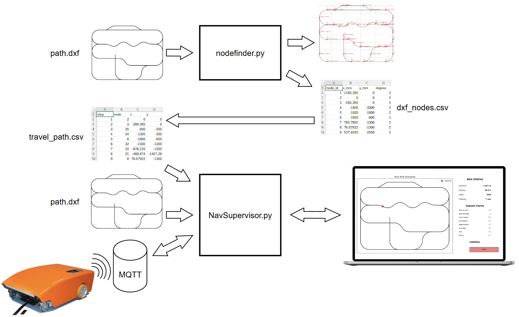
Supervisory Software Components
The reference path is defined as a 2D drawing in DXF format. The DXF is created at 1:1 scale and represents the physical magnetic tape layout installed on the floor. This drawing is used as the geometric reference for visualization only; it is not downloaded to the robot.
A preprocessing step is performed using the script nodefinder.py. This script parses the DXF file, identifies the geometric nodes of the path (line endpoints, arc transitions, and junctions), and displays the path together with the detected node positions. From this analysis, a CSV file is generated containing the coordinates of all identified nodes in the drawing reference frame.
Based on this node list, a separate file, travel_path.xlsx, is created manually. This file defines the ordered sequence of nodes that correspond to the actual route the AGV will follow. This step allows the same physical drawing to support multiple routes without modifying the DXF or the robot firmware.
The main supervisory application, EQBotcontrol.py, loads the DXF file and renders the track on screen. It also loads the travel_path.xlsx file to establish the logical travel order along the path. The application then connects to the MQTT broker to receive telemetry published by the AGV controller.
The primary input from the robot is the traveled distance, derived from encoder feedback and transmitted via MQTT. Using this distance information, the supervisor interpolates the robot position along the ordered node list and updates the on-screen position marker accordingly. This results in a moving indicator that reflects the AGV’s progression along the displayed track.
In addition to position visualization, the supervisor displays key operational data such as total distance traveled, battery voltage, current state (idle, run, docking, charging), tracking error, and magnetic sensor status. A basic control interface is provided to issue supervisory commands, such as run or stop, via MQTT.
This architecture keeps the supervisory software simple and deterministic in its role. The PC application provides visualization, monitoring, and high-level control, while all real-time navigation and safety-related functions remain entirely on the embedded controller.
Conclusion
This application demonstrates that a magnetic-guided AGV can be implemented with a small number of components while maintaining predictable and robust behavior. By combining the MTS160 magnetic sensor with the EQSP32 controller and a disciplined software architecture, it is possible to achieve industrially relevant guidance, docking, and monitoring functions without complex localization systems or high-cost sensors.
Key Hardware Components References
Naviq MTS160 Magnetic Guide sensor: www.naviq.com
EQSP32 IoT MicroPLC: www.erqos.com
SBLG2360 Dual-Channel Motor Controller : www.roboteq.com